How hard could building a register be?
So when starting this project, I wanted to try to build some smaller component first to get used to what this project would feel like. By the metric of “smaller” I’m left with either some control logic or a basic register, and it didn’t feel right to do the control logic first. So, register it is.

|
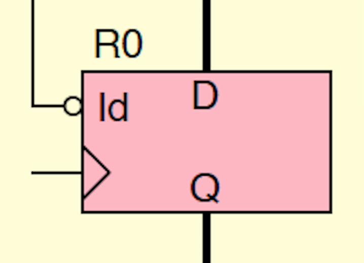
My goal here is to make a 16 bit register with a load line, asynchronous reset line, and a clock input as shown above. It should also have some way of outputting to a bus and a way of enabling that driver. Still though, if you’re thinking that it doesn’t sound so hard to do you’d be right. It felt too easy. After looking at the 7400 Series chips I found that there were a host of registers, flip flops and other storage devices. I won’t bother doing this as explicitly in the future, but lets go through the process of narrowing down possible chip options.
I started with everything on the wikipedia page List of 7400 series integrated circuits that has the words “Register” or “D flip flop” in the description. That list turned out to be 72 items long, so I’ll save space and not list that out here.
The next filter was finding out which of these parts are actually in stock. The project will almost certainly be SMD, and the best stocked supplier of 74XX series parts I’ve found has been Futurlec, so I’ll probably go with them. So what is left?
It’s these:
- 7474 - dual D positive edge triggered flip-flop, asynchronous preset and clear
- 74164 - 8-bit parallel-out serial shift register, asynchronous clear
- 74165 - 8-bit serial shift register, parallel load, complementary outputs
- 74173 - quad D flip-flop, three-state outputs and asynchronous clear
- 74174 - hex D flip-flop, common asynchronous clear
- 74175 - quad D edge-triggered flip-flop, complementary outputs and asynchronous clear
- 74194 - 4-bit bidirectional universal shift register
- 74195 - 4-bit parallel-access shift register
- 74374 - octal register, three-state outputs
- 74595 - 8-bit shift registers, output latches, three-state parallel outputs
So do any of these fit what I need? I’ll start by taking out everything that can’t do parallel-in/parallel-out data loading/storing (74164, 74165, 74194, 74595). Next, I’ll take out the flip-flops and registers that don’t have an enable/load signal, otherwise I’d have to add that myself (74174, 74175, 74374).
That leaves us with three options:
- 7474 - dual D positive edge triggered flip-flop, asynchronous preset and clear
- 74173 - quad D flip-flop, three-state outputs and asynchronous clear
- 74195 - 4-bit parallel-access shift register
The 7474 doesn’t look appealing because despite its wealth of features, it only has two flip flops meaning I would need 8 of them to make a 16 bit register. Finally, between the 74173, and the 74195, it came down to the fact that I like the pin locations on the 74173 more, and hopefully that will help when laying out the PCB.
Two thoughts enter my head as I pick this part out: “Am I making this too easy?” and “How do I make this look nice and interface nicely?”. After much mental deliberation, I decided that no, this isn’t “too easy”. It will still be over a dozen interconnected circuit boards and an it will engineering challenge even if the register and future components are mostly done for me by the 7400 Series chips. It is also fine because doing it out of any middle level components would arguably be just as much of a cop-out and less worthwhile, and doing it out of gates alone would be crazy.

|
As for the second question, I decide that I should have lights to display the register’s contents and that I need to come up with an easy way to connect the bus to the register and back. Looking to the inspiration I had for this whole project, the 8 bit computer youtube series, I find his videos on registers. (I actually end up watching the whole series and end up getting a few ideas) The first thing I notice though is that he has also gone with the 74173 chip, the second thing is that he makes a very good point: If I want to have a tri-state output for my register AND be able to see the output all the time, I need to add the tri-state functionality myself, otherwise I won’t see the register value when I’m not driving the bus. I follow pretty much exactly what he did at this point and decide to add two “74245 - octal bus transceiver, non-inverting three-state output” chips to separately drive the bus while keeping the output from the LEDs always on.
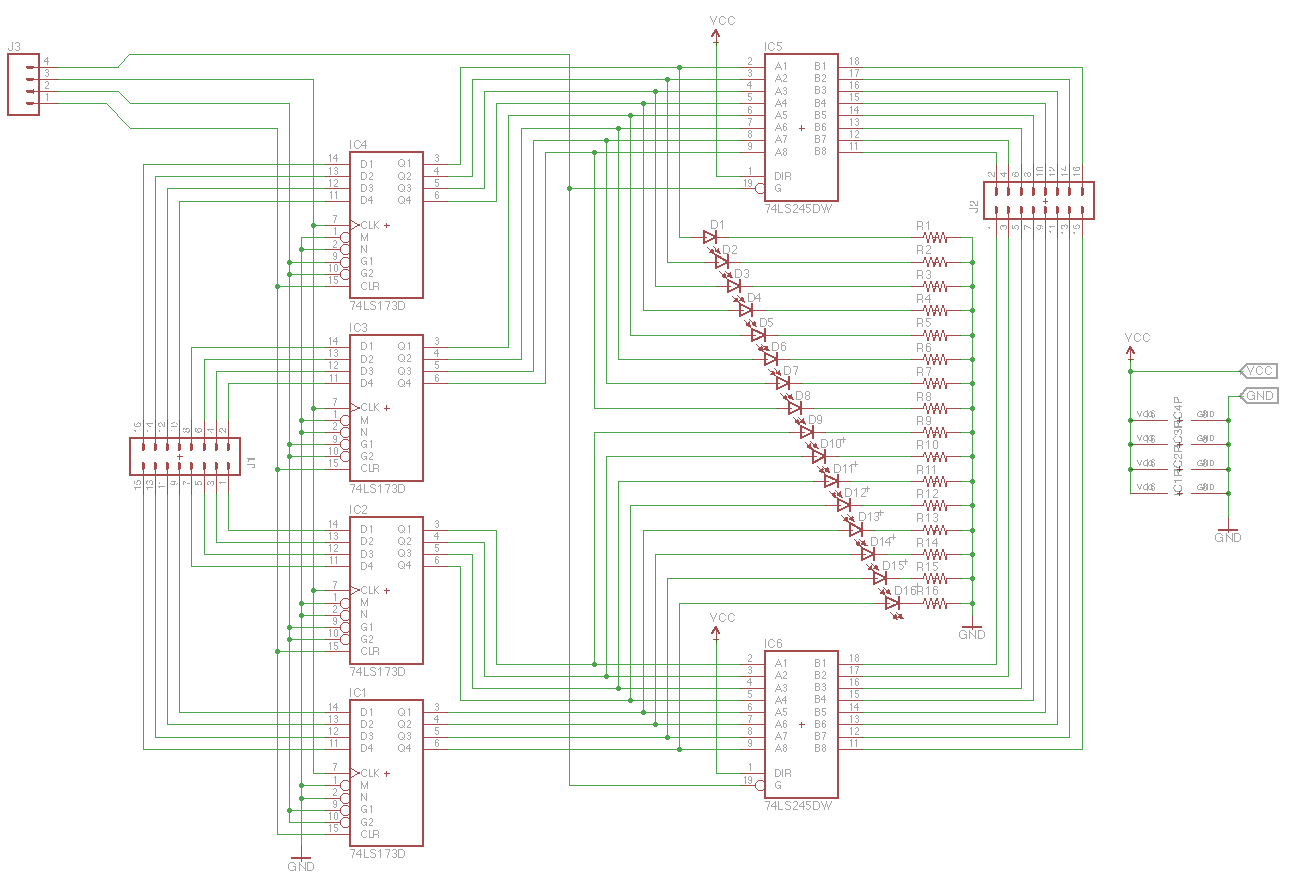
After deciding on a simple 2x8 pin header for the 16 bit bus connector, I draw up a simple first schematic:

|
That isn’t bad at all! The 4 pin header in the top left contains the 4 control signals (load, clear, clock, and output enable) Also, looking back now, I don’t love the LEDs in the middle of the two bus drivers, but I can change that later. I take a look at the board view and what needs to happen there and I decide it is time for a break. Similarly, looking at the length of this post I’ll stop this here and put the board layout and revisions into the next post.
- Dillon