I thought I was done with this…
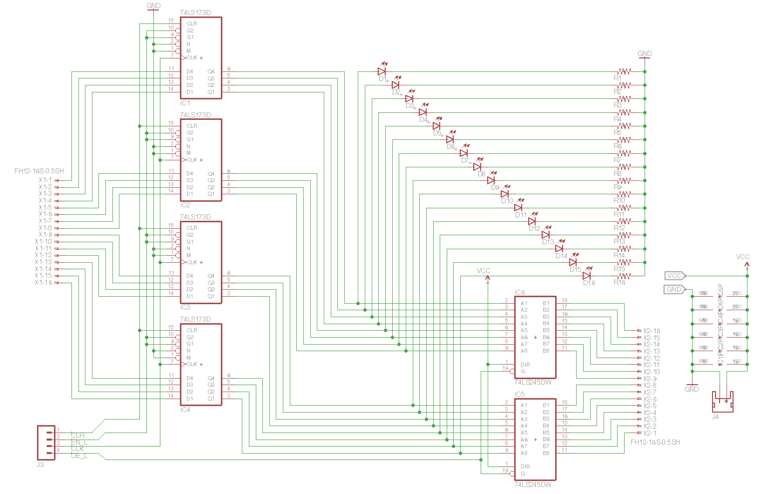
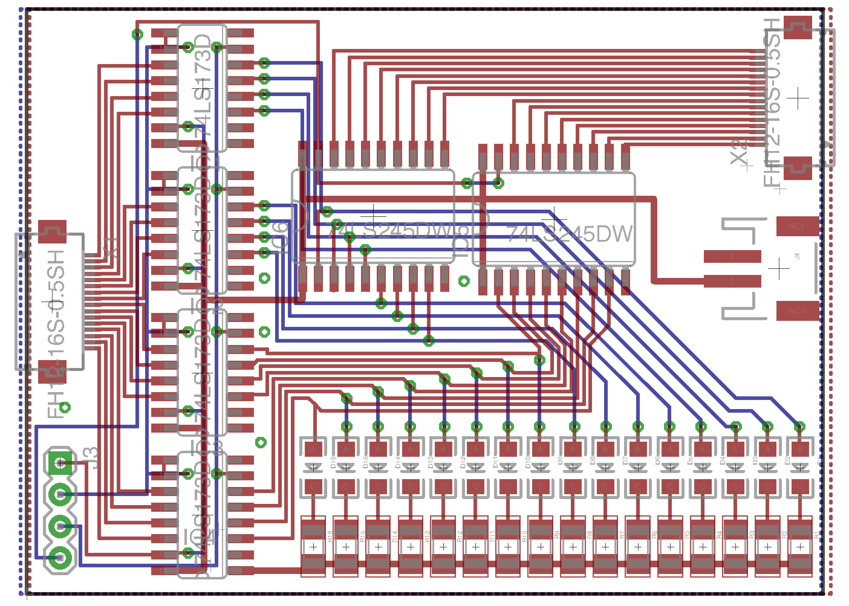
Like many new concepts to me, the first time doesn’t always end perfectly. In the last post I was talking about the new connectors I had picked out and how much I liked them. In eagle, the pins for the connector are numbered 1 to 16 and it made sense to me that if the first bit of the input was connected to the pin numbered “1”, then the first bit of the output should also be connected to the pin numbered “1”. I had this nice mental image that when things are plugged in, the cables between the two connectors would connect pin 1 to pin 1 all the way up through pin 16 to pin 16. Unfortunately just as I finished typing up the previous post, I realized this mental image is WRONG. When plugging two connectors into each other assuming a flat ribbon cable, the wires will naturally connect pin 1 to pin 16, pin 2 to pin 15, etc… This means I had to flip one of the connectors (it was easier to flip the output connector) and re-layout most of the board.
Here is what I came up with:

|
And the new board:

|
All of the circuitry in the registers is actually ignorant of the bit order, however in the final product, I would like the flow of information to go left to right, I would like the LEDs to read out with the MSB on the left, and I would like the bit order to read LSB on top in general. Placing these two constraints on the board alongside the routing meant that without redoing the entire board, the output header would be the one that is “counterintuitive”.
Well, I’m at least glad that I learned this on the first board of the project rather than on the last. I know in the previous post I said I’d move onto the ALU next, but what this incident made me realize is that I should lay out how this will roughly look put together to see if everything will be compatible. That is probably going to be what my next post is on, but then again, who knows, I didn’t expect to be writing this post.
- Dillon