“If you wish to make apple pie from scratch, you must first create the universe” -Carl Sagan
A disclaimer: There is not now, nor will there ever be anything dangerous about this project. This is not actually a bomb, just a game replica.
If you’re reading this and don’t know about this project or the game Keep Talking and Nobody Explodes you should check out either the project page or the announcement post.
This post will cover some of the basic decisions that were made about various parts of the project and the first module.
Communication
The very first thing that came to mind after planning the general design some modules is the location of the processing power and how things would communicate. A number of solutions came to mind. Maybe I would have one extremely power processor such as a raspberry pi controlling all aspects of everything or maybe each module should have its own less powerful chip such as an Atmega328. If I went with the distributed processing solution, what would be the responsibility of the controlling module and what would be the responsibility of the child module?
In the end I decided that each module would have an Atmega328p in the form of an Arduino Nano clone, and that each module would be responsible for as much as possible within it’s scope. That meant each module would control it’s I/O, check for win/lose conditions, and only communicate when it had reached some final state such as a solve or strike.
The next step was figuring out the physical/low level communication layer between the modules. I ruled out anything that required 2 or even 1 wire unique to each module as that could be as many as 12 or 24 I/O taken up just by communcation in the final design. So with SPI and individual serial lines ruled out I turned to I2C. The problem with I2C is that many of the child modules also had things like I2C displays meaning they needed to be both the I2C slave to the controller module and the I2C master to the display. After looking at a number of possibilites including a weird multi-master I2C setup and better microcontrollers with support for multiple I2C interfaces, I decided that I2C just wouldn’t work.
I finally arrived after a lot of searching at the concept of a “Multidrop UART Serial Bus”. It only used 2 pins per micro, could be used in conjunction with whatever other communication the micro needed for I/O, and didn’t require individual lines to each child. I ended up using this physical layer solution from Cool-Emerald. The problem with a solution like this is bus contention, which is where multiple devices try to write to the bus at the same time, often losing both messages in the process. Despite this, I still found that multi-drop serial would work best for my purposes and decided I’d just write my own layer to manage bus contention.
Borrowing from the designs of a few communication protocols I wrote the DSerial library. The README gives a good a summary as any:
The DSerial library implements a layer on top of any Arduino Stream
interface. The DSerial library operates with one master and many clients and in
addition to managing bus contention, it makes a best effort to guarantee that
each message will be delivered to the desired client exactly once. To this end,
it implements message-level parity checking, a pre-defined number of retries
upon failed delivery, and can determine which clients are alive on the network.
It’s not perfect, but it does what it needs to do well enough for this project.
Modularity
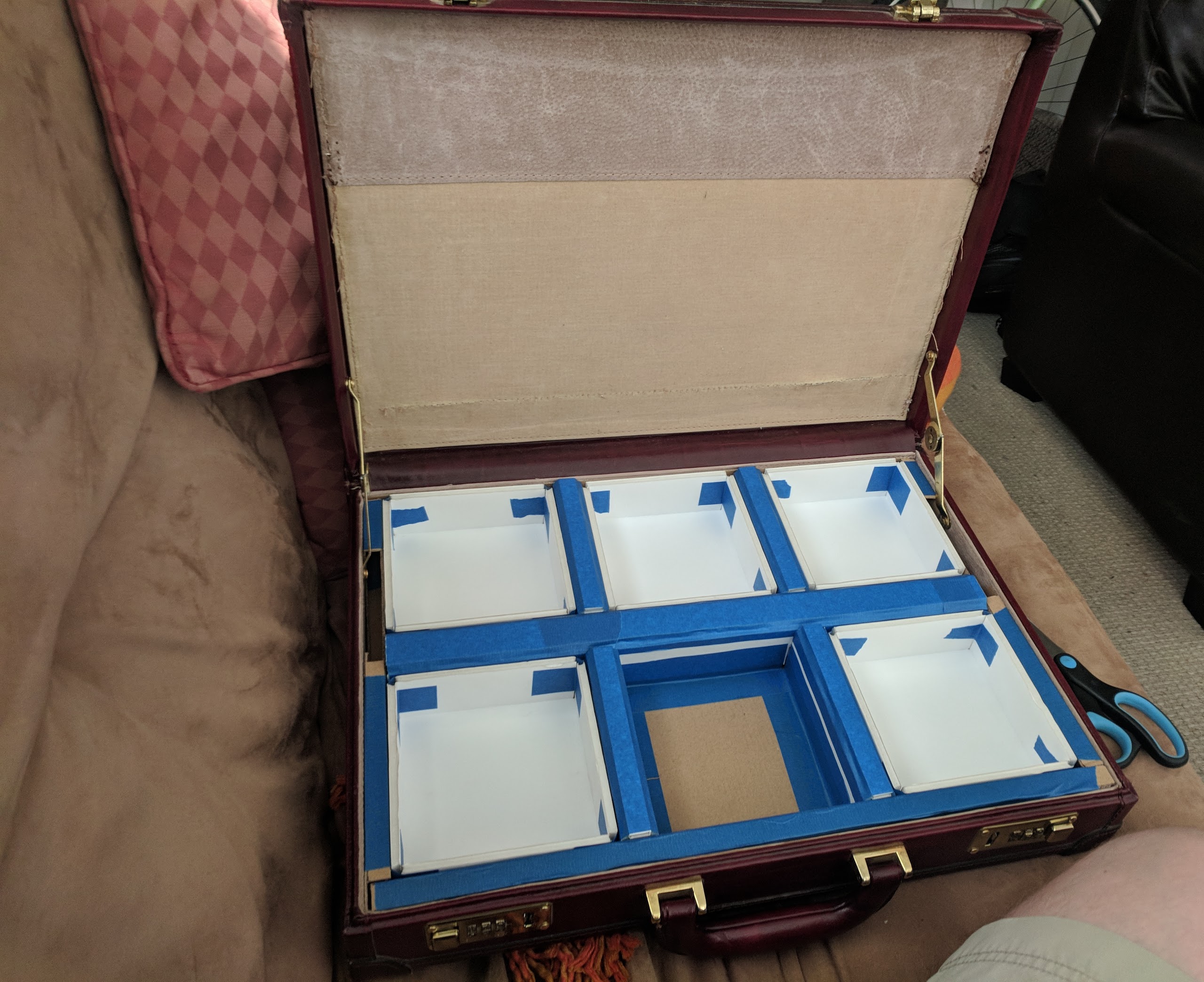
As the last post mentioned, I plan to have 17 total modules when this project is complete, a number impossible to properly showcase without the ability to swap modules on the fly. This meant the base had to have some way to nicely accept and hold the modules, as well as a relatively easy way for the modules to connect and disconnect. The first was easy enough, after a bit of measurement and some time on the laser cutter with some foamboard I had a quick and dirty modular system.

|
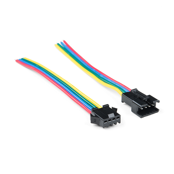
The second part, easy connecting and disconnecting of the modules gave me a bit more trouble. Each module needs 4 wires: power, ground, TX, RX. Looking at a bunch of 4 pin connectors, I originally wanted some sort backplane in the case that the modules would just plug into as they were pushed in, but that was quickly deemed infeasible for version 1. The next best thing I could find was connectors made for LED strips. They were directional, locking and small, which fit my needs perfectly.

|
First Modules
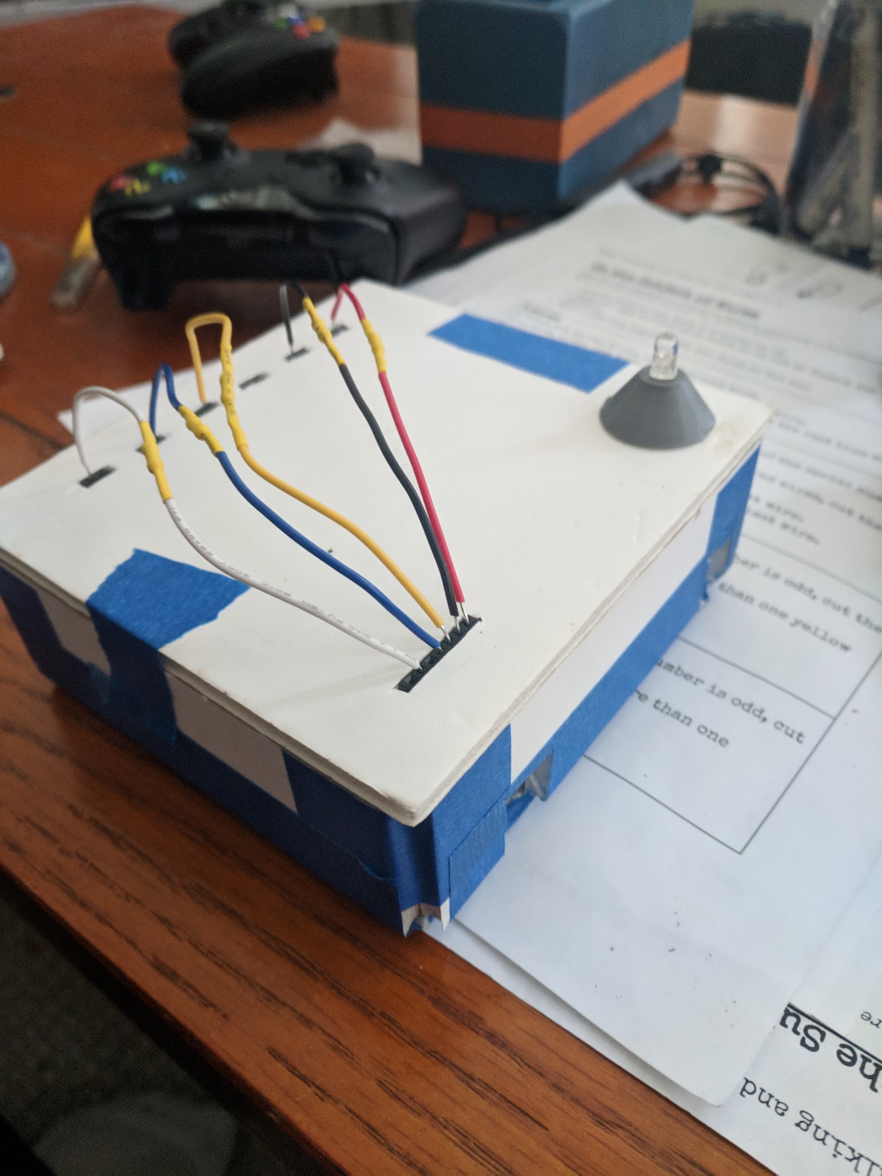
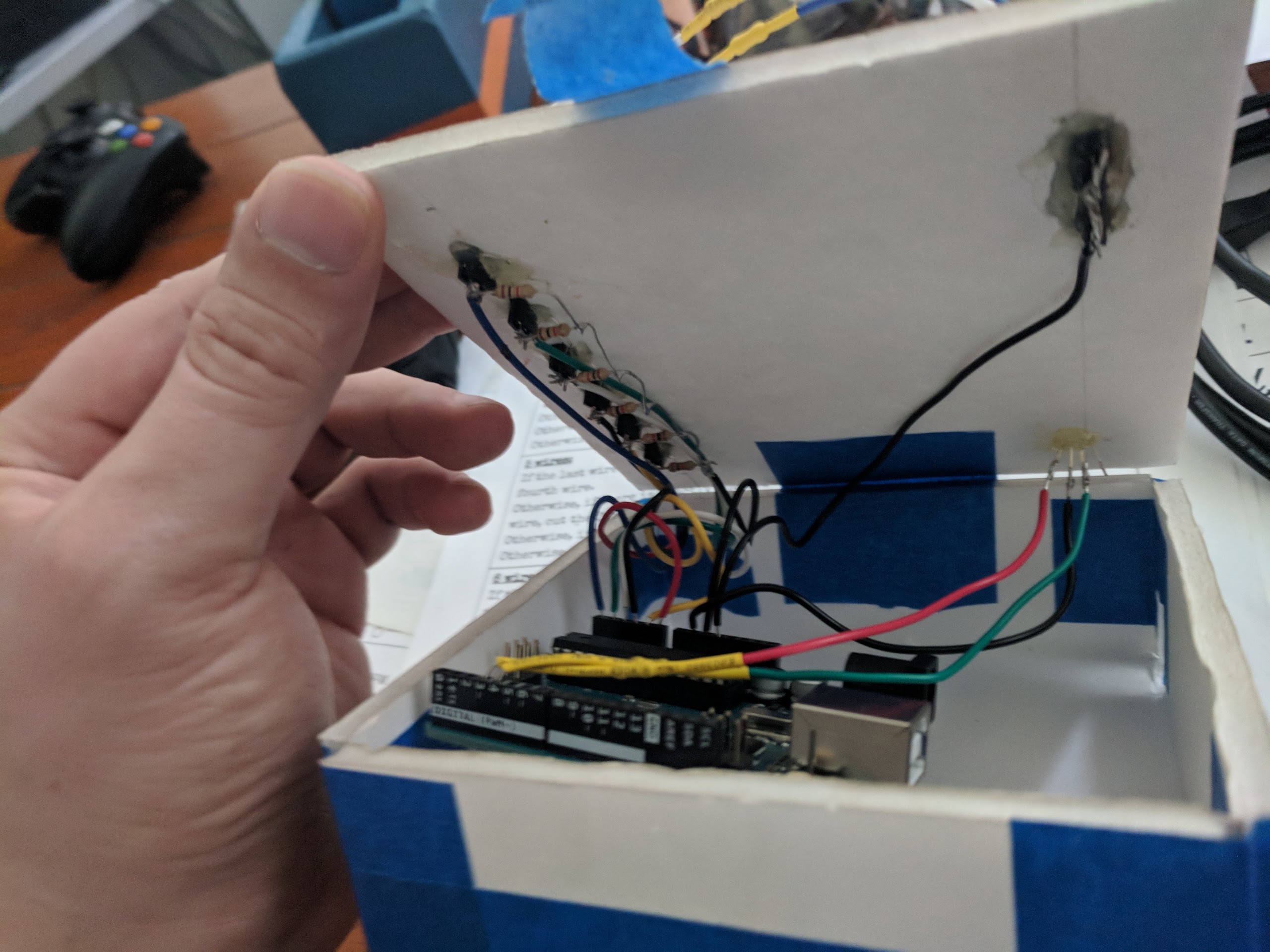
With the base details sorted out, I moved on to making my first module. There’s not a lot to say here, after poking some holes for female pin headers in some foamboard and soldering some pullup resistors, the basic wires module was done.

|

|
After some quick coding to recognize the wire colors by the resistors under the pictured yellow heatshrink, it was running and playable. It was nothing special, it didn’t talk to any other modules yet, and all that happened when you won was that a green led lit up, but it was progress and proof that maybe this could happen.
Posts about this project will continue next week, talking about debugging, other modules, PAX, and the future of the project. Stay tuned.
- Dillon